Tuesday, December 12, 2023

WHAT IS LIGHT RAIL? (Redefined)

Light Rail Defined

Tracks for light rail transit are generally constructed with the same types of materials used to construct “heavy rail,” “commuter rail,” and railroad freight systems. Also, light rail vehicles may be as massive as transit cars on heavy rail systems. Consequently, the term “light rail” is somewhat of an oxymoron and often misunderstood. Therefore, for the purposes of this book, it is appropriate to define light rail transit.

The ReDefined of light rail transit is:

An electric railway system characterized by its ability to operate single or multiple car consists along exclusive rights-of-way at ground level, on aerial structures, in subways or in streets, able to board and discharge passengers at station platforms or at street, track, or car-floor level and normally powered by overhead electrical wires.

To expand that definition:

  • Light rail is a system of electrically propelled passenger vehicles with steel wheels that propelled along a track constructed with steel rails.

  • Propulsion power is drawn from an overhead distribution wire by means of a pantograph other current collector and returned to the electrical substations through the rails.

  • The tracks and vehicles must be capable of sharing the streets with rubber-tired vehicular traffic and pedestrians. The track system may also be constructed within exclusive rights-ofway.

  • Vehicles are capable of negotiating curves as sharp as 25 meters [82 feet] and sometimes even sharper, in order to traverse city streets.

  • Vehicles are not constructed to structural criteria (primarily crashworthiness or “buff strength”) needed to share the track with much heavier railroad commuter and freight equipment.

Saturday, November 11, 2023

WHAT IS LIGHT RAIL?

Background

Light rail transit evolved from streetcar technology. Electric streetcars dominated urban transit in just about every significant city up through World War II. But once the war was over, “old-fashioned” trolley lines were converted to bus operation in droves, all in the name of “modernization.” By 1965, only a handful of legacy streetcar systems still survived.

The genesis of the terminology “light rail transit” dates to the late 1960s when planning efforts were underway at what was then called the Urban Mass Transit Administration (today’s Federal Transit Administration) to procure new vehicles for legacy trolley lines in Boston and San Francisco. The principals working on that program recognized that, because of the wholesale abandonment of streetcar lines in the previous two decades, the words “streetcar” and “trolley” had stigmas with likely negative political consequences for the program. Therefore, the term “light rail vehicle” was coined, borrowing from British vernacular.

Tuesday, October 10, 2023

Dynamic turbine reinspection intervals

LP rotor blade attachment dynamic reinspection

This dynamic reinspection analysis for low pressure turbine blade attachments considers two methods of crack propagation – stress corrosion cracking and low cycle fatigue. SCC is a well-documented industry phenomenon that occurs in wet steam environments with increased probability as the unit’s service hours exceed 150,000. The blade attachment area acts as a natural trap where chlorides can collect and concentrate. Crack growth rates are driven by a number of key factors including material yield strength, stage operating temperature, and steam chemistry. SCC is dependent on operating time and not cycles. On the other hand, LCF is caused by repeated stresses due to start and stop cycles. Because of this, different operating profiles lead to varied crack growth rates based on the phenomenon that is driving the crack.

The method for evaluating duty cycle dynamically utilizes fracture mechanics principles and assumes there is an initial flaw—either the largest flaw found in a prior inspection or the minimum detectable value from that inspection technique if the prior inspection yielded no reportable indications.

Crack propagation is considered as a combined rate from low cycle fatigue due to regular on/off cycles, low cycle fatigue from overspeed cycles, and hour dependent stress corrosion cracking. The resulting crack growth from each phenomenon is summed and compared as a total crack growth amount to the reinspection crack size. The reinspection crack size is calculated using fracture mechanics principles and conservative material properties and includes a safety factor to allow for safe operation between inspections.

The next two scenarios are provided to illustrate the concept and importance of considering both operating hours and cycles when determining low pressure turbine reinspection intervals. One of the most significant benefits in this type of automated analysis program is that only the operational hours and stop/starts need to be input in order to output a visual representation of crack progression.

Figure 1 shows an example of the crack propagation rates. The reinspection crack size is indicated with the solid red line. The dashed red line shows the calculated crack propagation based on the user inputted duty cycle. When the two lines meet is when a reinspection is required.

For this specific example (not a generic curve), the two major contributing crack growth rates (SCC and LCF) are shown in green and blue lines respectively. The circles reflect the amount of crack propagation due to SCC/operational hours (green) and LCF/cycles (blue) experienced to date. The scenario shown in Figure 1 shows a base loaded operation where most of the crack propagation has come from SCC (green) and there is only a small amount from LCF (blue). In this instance, the solid black line shows the calculated crack propagation is currently 73.8% of the way to the reinspection crack size.

To compare, Figure 2 shows the same unit but with an operational profile that focuses on cycling. It has three times as many cycles as the previous scenario and significantly fewer operational hours. However, crack propagation is still in a similar range. With a dynamic reinspection interval methodology, outages can be scheduled while taking into account the changes in operating profile.


HP Rotor Blade Attachment Dynamic Reinspection

Because HP blades are much smaller and typically do not see wet steam during operation, LCF and SCC are not traditionally the limiting mechanisms for rotor blade attachments. However, because HP blades operate in an elevated-temperature environment, they are susceptible to creep. Creep is a form of slow, continuous deformation that is inevitable with high temperature operation and based on operational time, stresses, and temperature. In a steam turbine, the HP and IP inlet stages are most at risk for creep—in fact any stage that sees temperature in the range of 900°F or higher is likely to accumulate creep damage over its operational life.

Inspection intervals for high temperature creep are often based off the assumption of full load operation at design steam temperatures. Thus, operation at low loads and below design steam temperatures can greatly reduce the rate of creep damage. Similarly, exceeding design steam conditions can significantly increase creep rates and reduce creep life. With a dynamic reinspection evaluation the actual operational hours and steam temperatures are considered to calculate expended creep life.

Using the operational stress and the actual temperature data, the Larson-Miller method can be used to estimate how much creep life has been consumed. The Larson-Miller equation relates temperature, time, and creep rupture stress to predict time to failure based on a stress level. This relationship is shown in Figure 3. By varying inlet temperature new creep consumption rates or creep lives can be calculated for a given stress level. Completing this type of analysis allows for evaluation of actual creep life expenditure based on a unit’s operation rather than a generic assumption. It can both prevent premature replacement of rotors and indicate if a rotor needs to be inspected more frequently to ensure reliable operation.


Conclusion

Both the LP and the HP dynamic inspection methods are designed to evaluate areas of life expenditure. Based on a unit’s actual operational profile and not assumed duty cycle, more representative inspection intervals can be determined frequently and updated inspection intervals set based on a specific life limiting parameter for a given design. If the unit experiences lower temperature operation than design or has a more base-loaded operating profile than the reinspection interval was set on, then the current reinspection intervals may be too frequent. However, if the unit is operating at higher than design conditions or is cycling much more frequently, then the reinspection intervals may need to be more frequent. A proactive approach to operational based damage mechanism evaluations allows for more realistic reinspection intervals for a given design type. Rachel Sweigart

Saturday, September 9, 2023

Five Grades of Automation.

The summary automation of rail transport into five Grades of Automation.
Grade of AutomationType of Train operation Setting train in motionStopping train Door closureOperation in event of Disruption
GoA 0On-Sight Train Operation DriverDriver DriverDriver
GoA 1ATP with driver DriverDriver DriverDriver
GoA 2 - STO Semi-automatic Train Operation (ATP and ATO with driver) AutomaticAutomatic DriverDriver
GoA 3 - DTO Driverless Train Operation AutomaticAutomatic Train attendant Train attendant
GoA 4 - UTO Unattended Train Operation AutomaticAutomatic AutomaticAutomatic

Tuesday, August 8, 2023

VFD induced draft fan coupling failure

Torsional vibration problems in rotating machinery can be difficult to recognize. Unlike radial vibration which can be easily measured with readily available sensors, torsional vibration is more difficult to measure because it involves the twisting of shafts while the machine is rotating. It can typically only be measured with special devices such as strain gauges or torsional lasers. As a result, torsional problems typically go unnoticed until something fails.

Variable frequency drives (VFDs) are commonly used to vary the speed of various types of rotating machinery to efficiently control the capacity. Typical machinery applications include pumps, fans, blowers and compressors. However, VFDs can induce dynamic torques which can excite torsional natural frequencies, leading to undetected failures.

It is not likely further testing will help with the understanding of the failure mechanism. While it may be possible to make VFD configuration changes, the VFD manufacturer has not been helpful in the failure investigation. So, this might end up being a trial and error process. It is also possible to change to a different VFD manufacturer or model. However, changing to a torsionally resilient type coupling is a simple change and has a high chance of solving the problem. Based on this, the decision was made to change to a torsionally resilient type coupling. A couple of different coupling types are being evaluated. It will be necessary to do a torsional rotordynamic analysis as part of the retrofit.

VFDs can also cause torsional vibration problems. And, these can be difficult to analyze. In some cases, field testing is needed. Even though the testing led to inconclusive results, it did show that high dynamic torque was not the problem. This provides the confidence that installing a more tolerant coupling will solve the problem.

Patrick J. Smith

Friday, July 7, 2023

Old Picture

Tuesday, June 6, 2023

Attack risk at the root

4 ways to address brand-critical safety, security and obsolescence challenges

Managing risk is ultimately about protecting your brand and reputation. Your approach to risk management should focus on where problems originate:

  • Equipment obsolescence:
    Modernizing production systems using the latest control and information technologies can help minimize unplanned downtime, support compliance with the latest standards and regulations, and play a major role in managing the other areas (quality, safety and security).

  • Quality:
    Harness the power of information buried within your operations to improve quality management and help confirm adherence to existing and emerging government regulations.

  • Safety:
    Safety must be addressed in three crucial areas – culture, compliance and capital. The upside: companies that experience fewer safety incidents have also been shown to have improved operational performance.

  • Security:
    As you embrace end-to-end connectivity across your facilities and enterprises, a comprehensive security approach helps protect people and intellectual property.

Friday, May 5, 2023

Make the Most of Modernization

Smart manufacturing is digitizing and transforming nearly every aspect of industrial operations.

Plants and systems that previously operated separate from each other can be integrated with end-to-end connectivity. Machines that had little or no visibility into their performance can be monitored in real time. Workers who were reliant on manually collected data and tribal knowledge can make better decisions with production intelligence, online support and mobile collaboration.

Key to making all of this possible is a modern network architecture — one that not only meets your immediate needs, but also addresses potential future challenges and anticipates future innovations and growth.

Tuesday, April 4, 2023

Key Design and Deployment Considerations

For most organizations, network modernization involves bringing together IT and operations technology (OT) systems into a converged network architecture. This creates a common, connected and standardized infrastructure in which people, processes and technologies can be seamlessly connected.

No modernization project will be the same. However, keep in mind some general considerations to help optimize your network design and proactively address risks.

  1. Collaborate Upfront.

    Modernizing a network infrastructure shouldn’t be a go-it-alone venture for IT or OT. Rather, it needs to be a collaborative effort that involves functional teams from across organizations.

    Early and open dialogue can help minimize any cultural differences by getting buy-in from all stakeholders. Most importantly, however, upfront collaboration is crucial to identifying potential risks and addressing them before they develop into problems.

    Some areas where collaboration is key include:

    • Determining what connections are needed between the manufacturing execution system (MES) and enterprise business systems so everyone has access to the information they need.

    • Designing the network such that maintenance can be done without disrupting production.

    • Coordinating safety and security efforts to help identify and mitigate potential risks that could arise from security or safety incidents.

  2. Use Design and Deployment Resources.

    Industry guidance and resources are invaluable during your network modernization project.

    Introduces the concepts and technologies you need to make the transition, while also providing tips on system design, configuration, implementation and troubleshooting.

  3. Choose the Right Protocol

    One of the most critical decisions you will make in designing your network infrastructure is selecting the right industrial Ethernet protocol.

    Today, manufacturing and industrial companies are seeking to capitalize on the proliferation of connected smart devices that make up the Industrial Internet of Things (IIoT). IIoT devices use the internet protocol (IP), which provides the common language for different devices to coexist and interoperate on the same network.

    Adoption of IIoT technologies will be a defining characteristic of the industrial sector for the next several years. Research firm Gartner, Inc. forecasts that the number of connected things worldwide will reach 20.8 billion by 2020. The technologies are expected to help manufacturers generate nearly $3.9 trillion in value through increased revenues and lower costs in the coming years.

    One such IIoT technology is EtherNet/IP™, an industrial automation protocol that harnesses the power of IP, allowing for the harmonious coexistence of all IP-connected devices. This includes devices designed for industrial and commercial use. Proprietary networking technologies with multiple isolated networks can’t support this cross-device connectivity, unless you make additional investments in gateways, protocol converters or proprietary switching.

  4. Use a Holistic Security Approach

    According to a recent report from BDO USA, 92% of manufacturers cited cybersecurity concerns in their 2016 SEC disclosures this year. What’s more, the U.S. Department of Homeland Security has reported that basic cybersecurity practices in many industrial organizations are “an afterthought or significantly less than needed.”

    Industrial organizations cannot ignore the fact that more connection points in a modern industrial IP network architecture also bring greater security risks.

    No single security product, technology or methodology can be expected to contain today’s massive threat landscape on its own. A security-through-obscurity approach is no longer sufficient. Instead, you need a holistic security approach to help protect your people, operations, intellectual property and other assets.

    Your industrial security program should start with a security assessment to identify risk areas and potential threats. From there, plan to deploy a defense-in-depth (DiD) security approach that establishes multiple layers of defense.

  5. Plan for the Future

    The infrastructure life cycle in the industrial automation space is typically between 15 and 20 years. However, can you imagine in 20 years what your operations will look like or how you will be using information given all the innovation that’s occurring today?

    This is why it’s important that your industrial network infrastructure addresses your current needs while also anticipating those of tomorrow.

    You may someday decide to adopt virtualization, for example, which can cut the cost of acquiring, deploying and maintaining servers. But it also increases the amount and type of traffic on an industrial network. As a result, your network infrastructure should be segmented into different virtual LANs to create smaller zones. You also will need an industrial demilitarized zone (IDMZ) with servers that can access the industrial zone.

    Likewise, incorporating remote access into your operations will require that your network architecture support video and other collaboration tools. Integrating mobile devices will require that the network supports tablet authentication and encryption.

    Workforce changes also should be considered. A modern industrial IP network infrastructure combined with a smart production approach will have a significant impact on your workers. It will require IT and OT professionals to have a full understanding of the converged environment, and will reshape roles for those responsible for developing and overseeing it.

Friday, March 3, 2023

Optimize network design using smart manufacturing to digitize and integrate the operations to meet immediate and future needs.

A modern industrial IP network infrastructure is increasingly essential for most manufacturers and industrial companies.

By using the latest networking technologies, breaking down data silos, and harnessing the power of greater connectivity and information sharing, you can make the potential of smart manufacturing a reality. This can help you make real-time operations decisions and improve productivity in new ways. Just a few examples include the following:

  • Timely data access can help you track key performance indicators (KPIs) and improve processes, and help maintenance technicians get ahead of downtime issues.

  • Mobile devices can put subject matter specialists exactly where they need to be the moment a problem arises.

  • Self-aware and system-aware assets can automatically make adjustments to optimize processes and keep production running, with less need for human intervention.

Beyond productivity, a modern industrial IP network architecture also can help in other key areas.

The ability to access and analyze safety-system data, for example, can help managers better understand risks, enhance safety and ease compliance. Mobile devices can deliver information to workers in a familiar and convenient format. And the ability to track virtually every point in a product’s life cycle — from raw-ingredient receipt to supply-chain shipments — can help improve quality and on-time deliveries.

Thursday, February 2, 2023

Manual and Automatic

In process control, the term "mode" is used in two contexts:

  • Control modes. These are the proportional, integral, and derivative modes.

  • Operational modes. These are manual and automatic modes.

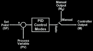
As illustrated in Figure above, the significance of the automatic/manual selection is as follows

  • Manual. The value for the controller output is specified by the process operator. The PID calculations are not performed. This mode is sometimes called "open loop" as the loop is broken at the auto/manual switch within the controller.

  • Automatic (or just "auto" ). The value for the controller output is the result of the PID calculations being performed for the purpose of automatic control. This mode is sometimes called "closed loop".

On switching the mode from manual to automatic, a smooth transition called "bumpless transfer" is desired; specifically, the value of the controller output the instant after the switch is to be the same as the value of the controller output just prior to the switch. This approach requires that the PID control equation be properly initialized or "balanced".

Sunday, January 1, 2023

Block diagram of a control loop


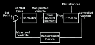
The Control Loop. The information flow in the block diagram in Figure below takes the form of a loop:


  1. A change in either the flow through the control valve or one of the process disturbances leads to a change in the controlled variable.

  2. The change in controlled variable is sensed by the measurement device, which changes the measured variable.

  3. The control error is the difference between the set point and the measured variable. Therefore, a change in either the set point or the measured variable leads to a change in the control error.

  4. The controller responds to a change in the control error by changing the manipulated variable (or valve position).

  5. A change in the valve position leads to a change in the fl ow through the control valve, which is one of the inputs to the process.


As the measured variable is "feed back" to be compared with the set point, the term "feedback control" is commonly applied to such loops.